
IMU
I don't want to explain what an IMU is. There is a lot of very good documentation on internet. We have just to remember that is used to know the orientation and position of a moving vehicle in the 3D space. In my indoor robot I've used just odometry because it is supposed to travel on a good and flat floor. Moving outdoor is not so simple, the wheels can slip or bump introducing a big, cumulative error, particularly on orientation. The odometry must be integrated with something else that returns the orientation with as much precision we can.
The basic version of IMU is the 6 DOF (Degrees Of Freedom), that means it is equipped with a 3 axis accelerometer and a 3 axis gyro. By the fusion of the acceleration and rotation measurements, with a lot of maths, it returns the position in space of the vehicle,
something similar to pitch, roll and yaw. Adding a 3 axis magnetometer we have the so-called 9 DOF IMU. Each sensor has its own peculiarity (long term drift but short term stability, short term error but good average value over the time and so on). By the odometry, the fusion of the three sensors and adding a GPS we can have a precision close to 0.5% according to the tests done by David P. Anderson on his jBot.
Look at his documentation for a detailed explanation.
Some other modifications have be done to the original MatrixPilot code getting the basic concepts from some branches in Google Code repository, a rich source to draw from for learning how real embedded programming is. The clock has been enhanced to 40MHz, the I2C protocol originally used only for magnetometer, is used now for communications with dsNav too, allowing this motor controller board to compute dead-reckoning using IMU yaw informations instead of using just wheel/encoder odometry, not reliable enough off-road.
A GPS data conversion library is used for internal conversion from GPS TOW and WEEKS number to a more human readable date
and time for GUI presentation. This must be used carefully to avoid too much CPU load.
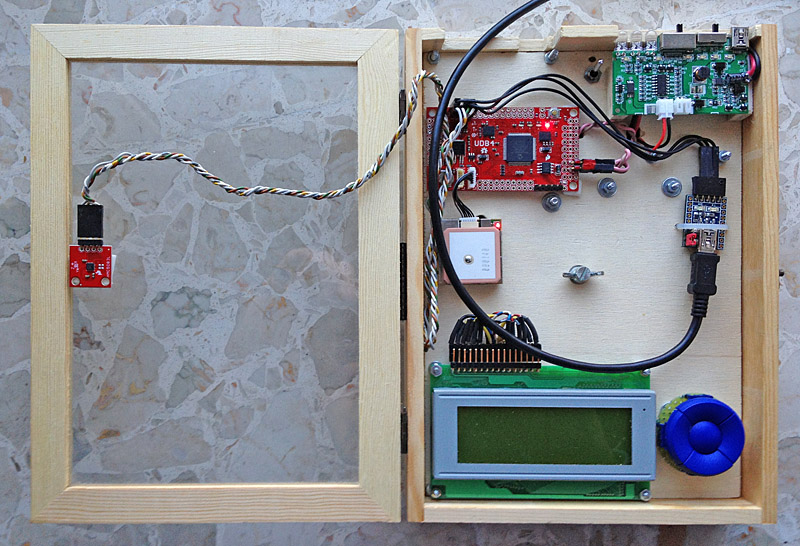
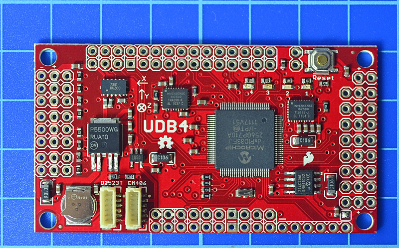
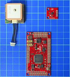
As already mentioned I would like to use this board to better understand what is behind the whole IMU theory. In order to have much more freedom I've mounted the UDB4 and it's peripherals on a self powered test set box, recycled from a previous experiment of mine. The Magnetometer is attached on purpose far away from magnetic parts to reduce interferences.
A first look to the UDB4 software has shown a very well organized an documented code. I'm going to learn a lot of things!
The whole MPLAB X project
of my porting from Bill Premerlani MatrixPilot software
is available as an open source at
Google code repository
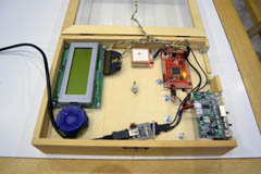
At the left a short movie that shows a simple test.