dsNavCon
The 12 AA NiMh elements battery pack was broken once more. It is the good moment to revisit the original project. At current days the LiPo technology is really mature. A lot of different packs are available at a good price. The LiPo chargers price drops down too. I've found a 14,4V @ 2100mAh pack that fits perfectly in the battery holder originally designed for the AA elements with 100 grams less.
Ok, let me describe what I've changed to optimize the power supply.
This LiPo battery pack is, theoretically, smaller than the NiMh one (2100mAh vs. 2700mAh). In practice the lower internal resistance on the LiPo leads it to a similar duration, at least. But, because the load is increased time by time adding circuits and circuits to my robot, I want to reduce at minimum the wasted energy. It's still a good idea to use a double step reduction to achieve the 5V and 3.3V power supplies for the boards starting from the motor power supply. It is useful to isolate motors noise and to concentrate the heat sink in a single place, but the linear regulators waste too much energy and became too hot.
Right now there are a lot of switching regulator ICs with high efficiency and easy to use. Lowering the 14.4V batteries voltage to 7V with an efficiency of 95% and, then, using LDO regulators on each board, has a triple effect: half of the current drained from batteries, very low heat generation, no problem with the ripple even for the sensitive analog circuits.
The LiPo batteries are more sensitive to charge and discharge cycles than NiMh. Continuing the charge when not needed can cause the pack explode. Discharging too much can permanently damage it. But this is no more a problem. A good LiPo charger can be purchased everywhere at low price. To monitor the discharge status an AD port of an MCU can be dedicated to avoid permanent damages to the pack.
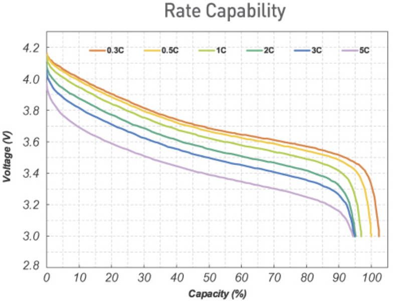
The discharge curve is precise and clear, it's easy to monitor the status of the battery defining some thresholds.
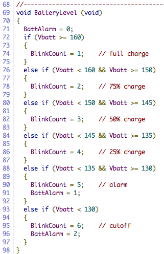
To the side a very simple code to monitor the battery status. The warning LED blinks at different rates according to the battery status. Below 13.5V an audible alarm is triggered too. When battery voltage is below 13V the board sends an halt command to the navigation board switching off the motors.
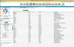
One of the best suppliers for this kind of devices is National Instruments, with a lot of different Ics, also available as samples, and a very good on line tool to design the circuit on your specific needs: WEBENCH® Power Designer
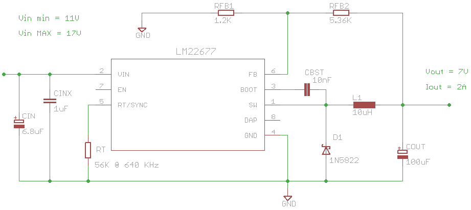
With the aid of the comparison tables was easy to find the device that fits my needs: LM22677 a 5A SIMPLE SWITCHER, Step-Down Voltage regulator.
With an operating frequency of up to 1MHz it requires a small inductor to have high efficiency and a low ripple.
After entering your values, the tool returns the schematic diagram, the bill of materials, the estimated parameters and also the thermal map. It's important to strictly follow their specifications on which kind of components to use (be careful to the low ESR capacitor) and how to design your board.
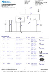
After some modifications to adapt the values to the components I had in my drawers, I've realized this Eagle schematic diagram.
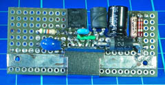
The circuit is so simple than can be easily realized on a perfboard. This keeps the profile of the boards low enough to allow the mounting on the same battery holder than before.
The elastic fast clip keeps the IC tightened to the copper band. Both clip and band act as heat sink to maintain the temperature low. Thanks to the high efficiency of the regulator this kind of heat sink is more than enough to dissipate the low amount of energy wasted.
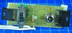
The switch and plugs board that accommodates all the inputs and outputs of the power.
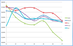
After the circuit has been realized, I've done some measurements to verify the theoretical
values obtained with WEBENCH® Power Designer.
With the help of this Switching Efficiency spreadsheet I've plotted this chart.
Guess what! The measured values are very similar to the computed ones.
Higher the output power higher the efficiency. Only the lowest output current curve shows an efficiency lower than 94% but, any case, higher than 90%.
I've achieved my goal the current drained from all the board in my robot was reduced by half and the heat sink in cold.