dsNavCon
The diagram to the left shows the overall architecture of the control procedures of this board and the navigation strategies applied.
The motor controllers can be seen as black boxes that take care of the speed of the wheels. The supervisor sends them the reference speed (VeldDesX: desired velocity). The Input Capture modules of the microcontrollers get pulses from the encoders connected to the motor axis and derive the rotational speed of the motors (VelMesX: measured velocity). Combining every 1ms this values in the PID control "Speed PID" we obtain the right PWM value to keep the desired speed of each single wheel.
The QEI (Quadrature Encoder Interface) modules get both the A and B pulses from the encoders and give back to the supervisor the traveling direction and the number of pulses in 4x mode (counting the rising and falling edges of signal A and signal B: 2 x 2 = 4) .
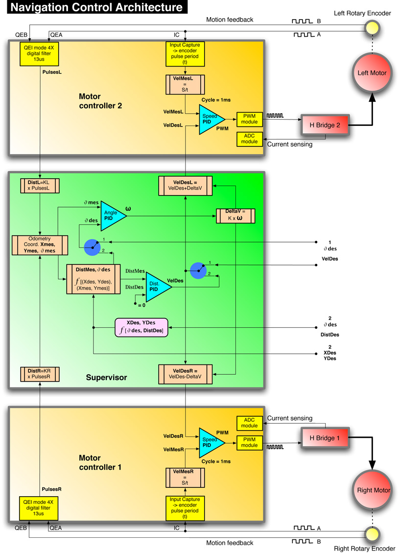
Multiplying the number of pulses by a K that indicates the space traveled for each single encoder pulse, we obtain the distance traveled by right and left wheels every 10ms. The supervisor combines this traveling informations and applies the dead reckoning procedure already described in order to obtain the measured position coordinates of the bot: Xmes, Ymes, θMes (orientation angle).
The supervisor receives navigation command from outside by serial interface (telemetry) or by I2C interface (main board). Different strategies can be applied:
A - travel at a given speed in a given direction (VelDes, θDes).
B - travel toward a given point with coordinates XDes, YDes.
C - travel for a given distance in a given direction (DistDes, θDes).
Mode A: with the "logical control switches" in position 1, only the PID control "Angle PID" is used on the supervisor. This one combines the desired angle θDes with the measured angle θMes calculated by odometry procedure, in order to obtain the value of the rotation angular speed ω of the vehicle around its vertical axis, needed to correct the orientation error.
The value of DeltaV is proportional to ω. It's added to VelDes to obtain the speed of the left wheel and subtracted to VelDes to obtain the speed of the right wheel, in order to keep the heading corresponding to θDes value, while the center of the robot is still traveling at VelDes speed.
Mode B: with the "logical control switches" in position 2, the desired speed VelDes is calculated by the PID control "Dist PID" and it is used as in mode A. The measured input for this PID (DistMes) is computed as a function of the current coordinates and the destination coordinates. The desired orientation angle θDes also comes from the same procedure and it's used as reference input for "Angle PID". The reference input for "Dist PID" is 0, meaning that the destination is reached. With ω and VelDes available, the speed control of the wheels runs as in mode A.
Mode C: with the "logical control switches" in position 2, the destination cordinates Xdes, Ydes are computed once at the beginning as a function of input parameters DistDes, θDes. After that everything goes as in mode B.
Below some C language code as an example of how to implement the orientation algorithm.
Code Example
void Orientation(void)
{
int DeltaVel; // difference in speed between the wheels to rotate
float Error;
ORIENTATION_FLAG = 0; // it will be restarted by DeadReckoning()
if (Angle < 0) Angle += TWOPI; // keep angle value positive
if (Theta < 0) Theta += TWOPI;
Error = Theta - Angle; // measured angle - desired angle
/* search for the best direction to correct error.
With this optimization, the rotation to point to the desired orientation, will never be
greater than PI rad (180 degrees) positive (CW) or negative (CCW).*/
if (Error > PI)
{
Error -= TWOPI;
}
else if (Error < -PI)
{
Error += TWOPI;
}
/* ref value translated to 0.
The previous optimizations already returns the error value between measured and reference values. This value can be used as "mes" input of PID if "ref" is set to 0. */
ANGLE_PID_DES = 0;
/* current error.
In order to work with fractional variables, needed by PID function, the value of the angle is normalized to a half circle angle (PI radians), so 0.25 means a PI/4 angle (45 deg),
0.5 means a PI/2 angle (90 deg) and so on. */
ANGLE_PID_MES = Q15(Error/PI);
PID(&AnglePIDstruct); // PID control execution
/* MAX delta in int = 256
This is the limit for Angle PID correction, the maximum amount of speed to add or subtract to the mean speed value (VelDesM) to obtain the speed of each wheel(VelDes[R], VelDes[L]) in order to have the desired rotation of the bot.
To convert fract to int it requires a division by 2^15. To keep the limit at 256 it requires a multiplication by 2^8, so >>15 + <<8 = >>7 */
DeltaVel = (ANGLE_PID_OUT >> 7);
/* As aforementioned, the rotation angular velocity is obtained adding DeltaV to the speed of left wheel and subtracting it to the speed of right wheel, with geographic convention
(CW = positive) .
If the speed of one wheel exceeds positive or negative maximum controllable speed, that
speed will be set to MAX_ROT_SPEED and the speed of the other wheel will be set to
(MAX_ROT_SPEED + or - (2*DeltaV)) resulting in a lower VelDesM.*/
VelDes[R] = VelDesM - DeltaVel;
VelDes[L] = VelDesM + DeltaVel;
if (VelDes[R] > MAX_ROT_SPEED)
{
VelDes[R] = MAX_ROT_SPEED;
VelDes[L] = MAX_ROT_SPEED + (DeltaVel << 1);
}
else if (VelDes[R] < -MAX_ROT_SPEED)
{
VelDes[R] = -MAX_ROT_SPEED;
VelDes[L] = -MAX_ROT_SPEED + (DeltaVel << 1);
}
else if (VelDes[L] > MAX_ROT_SPEED)
{
VelDes[L] = MAX_ROT_SPEED;
VelDes[R] = MAX_ROT_SPEED - (DeltaVel << 1);
}
else if (VelDes[L] < -MAX_ROT_SPEED)
{
VelDes[L] = -MAX_ROT_SPEED;
VelDes[R] = -MAX_ROT_SPEED - (DeltaVel << 1);
}
SendVelStatus = 1; // Start sending VelDes[x] to MCs
}
To the right a link to an example of path followed by the bot in a real telemetry experiment. It was in an early stage of PIDs K parameters calibration. It can be seen as the curves were too "smooth" since it required a long time to reach the desired orientation and there still was some error between reference angle (set on the knob) and measured angle (read on the gauge).
Fortunately the different PIDs (speed, orientation, distance) are indipendent each other simplifying the K parameters calibration procedure, therefore it was not difficult to obtain a much better response of the system.