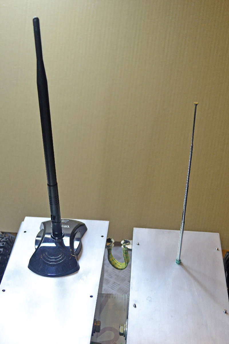
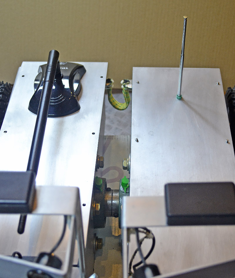
Both the antennas can be lowered down to reduce the size during the storage or tansportation...
The safety remote control antenna mounted on the left hull.
Regarding the safety I've already written this in the communication software description:
 |
The safety is a very important issue for an autonomous vehicle, both for its integrity and for the human health. A special attention has been applied on every board software to prevent "blind travel". On each board the internal watchdog system or something similar, has been used to keep the board in a safe state if the communication with other boards is lost for any reason. The startup condition for all the boards is designed to have motors halted until a higher level order arrives. |
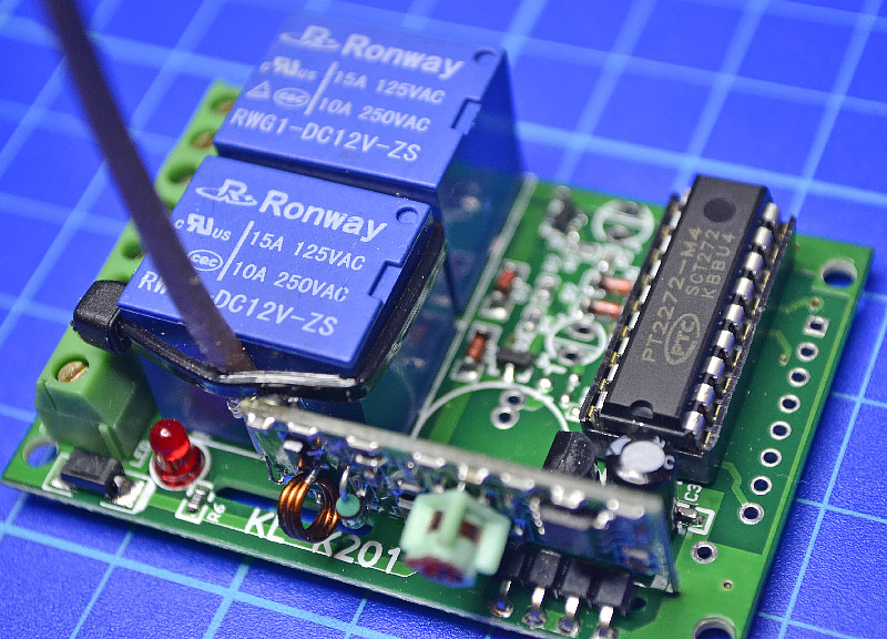
The receiver board contains the Radio Frequency part, the decoder circuit and the power driver. The decoder is a common PT2272 IC. It is not a very sophisticated decoder but the number of possible codes consents a security level much more higher than a standard Yale key-lock. The code is modifiable by soldering the pads on the bottom side of the PCB to high or low rails. Pay attention to have the same code in both TX and RX boards.
The power circuit is realized with two robust relays (one for each channel) both provided with normally-open and normally-closed contacts.

Safety Remote Control
What about, in fact, if some software module goes crazy or some communication between different boards fails? And what about an hardware module (H-bridge or encoder for example) keep the power at maximum levels to one or more motors? Are all the automatic fault detection systems enough? If not it could be difficult to run behind the rover trying to push the hardware switch off button.
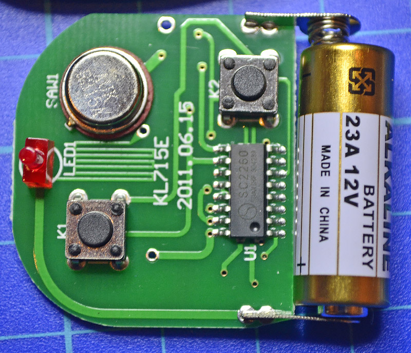
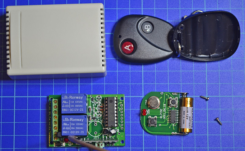
The simplest way, without reinventing the wheel, to remotely control an electric circuit, is a remote door opener. A very cheap and efficient two channel control.
Let's take a look inside. opening both the TX and RX boxes, we can easily understand the circuits, that both use some common components.
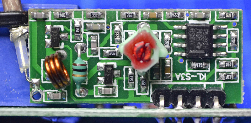
The RF subsystem is a super-regenerative receiver. This simple circuit, just two active devices, is a very sensitive receiver but with a lack of selectivity. This characteristic is not so important in this case because the reliability is achieved by the digital decoder filtering.
The detected signal is amplified by a LM358 double operational amplifier before being entered into the decoder.
Maybe I'm too anxious but I prefer to have full control on my rover. An emergency, autonomous system, with a dedicated communication channel, able to completely switch off the Low Level Supervisor, and therefore all the electronics inside the rover, can calm my anxiety and add a good level of safety to the whole robot.
Pressing for some seconds the B button a soft switch-off is performed, in the same way as the green button do. The red A button is for the high emergencies, immediate, hardware switch-off (as well as the red button).
The
SW switch-off drives both LLS and HLS to a graceful shutdown without the risks of file system corruption. The HW switch off could be less safe on the file corruption point of view but safer for possible hard damages in case of faults.
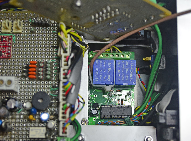
The board installed on the robot below the rear-left H-bridge.
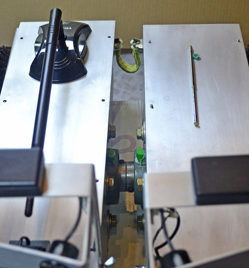
...or even completely removed.