updated on 24-12-2012
Display
The I2C slave protocol for the display
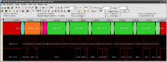
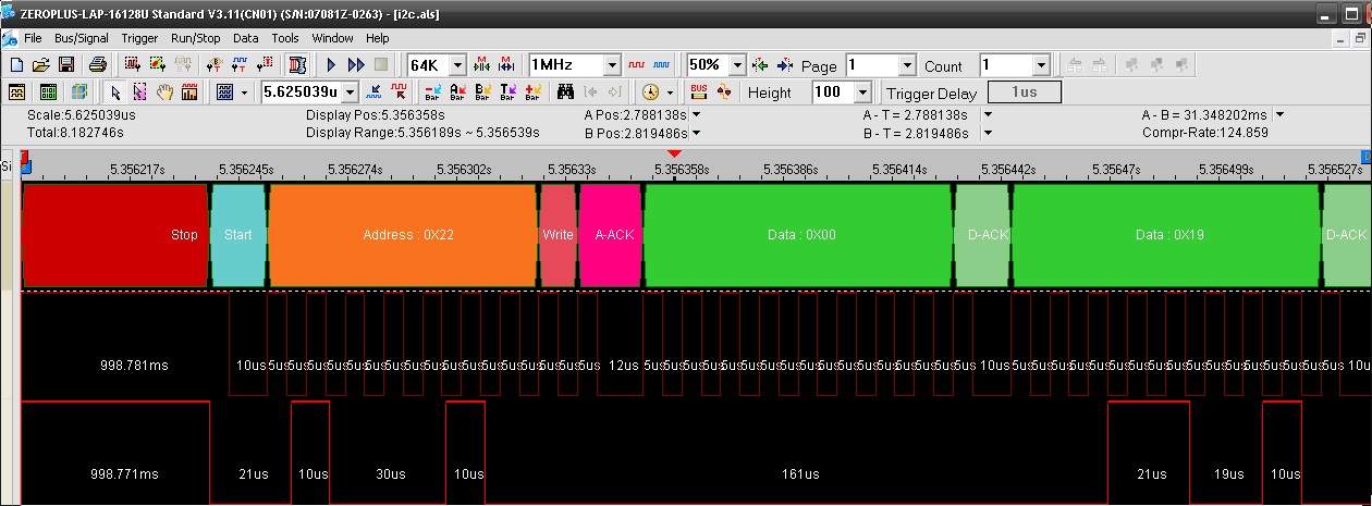
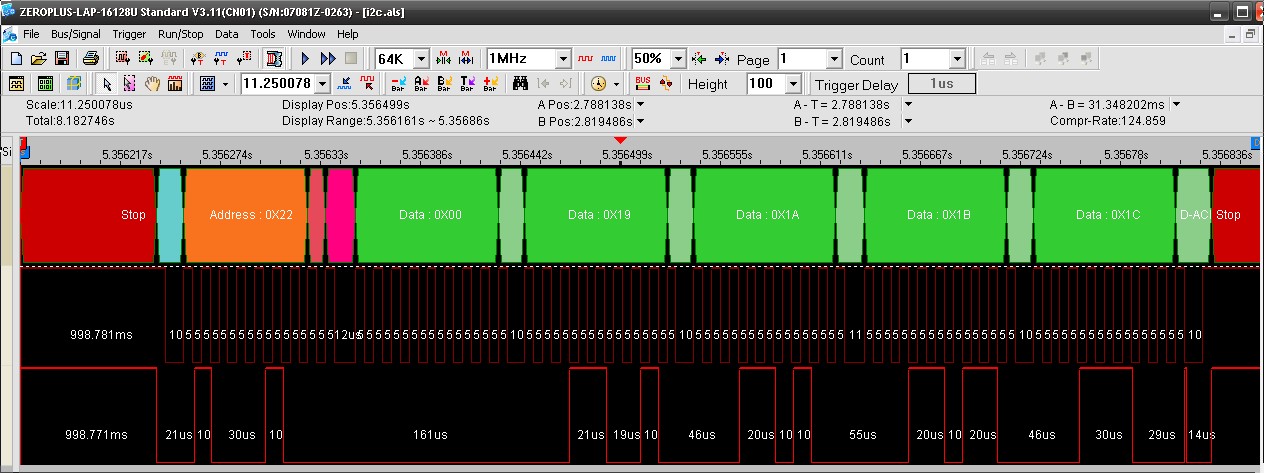
Protocol Analyzer view of an entire Write sequence for 4 bytes, starting from index 0 of the registers array.
The
blog is very clear: the Microchip library simply doesn't work:
Now you can play with this code all you want adjusting timing, Ack and Nack sequencing, delays, etc... but ultimately it will not do what you would like it to do / think it should do. Why? Looking into the C18 I2C libraries themselves you will see that some of the functions will only work in MASTER mode, or put simply they were not designed to be used in SLAVE mode. This is where most of my time was wasted.
Now you can play with this code all you want adjusting timing, Ack and Nack sequencing, delays, etc... but ultimately it will not do what you would like it to do / think it should do. Why? Looking into the C18 I2C libraries themselves you will see that some of the functions will only work in MASTER mode, or put simply they were not designed to be used in SLAVE mode. This is where most of my time was wasted.
the only way to make such a program working is by using the
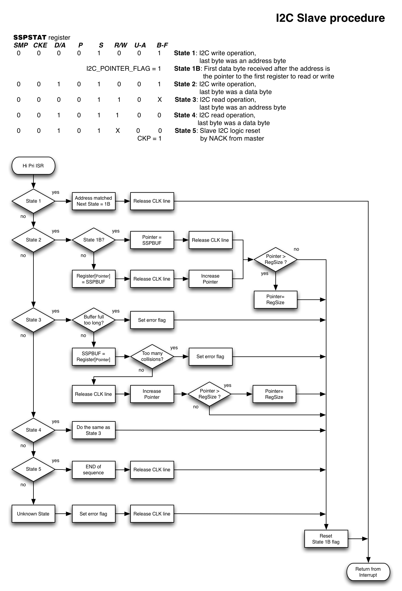
AN734 mode, possibly porting the original ASM code to C language. This application note was published in 2008 again, because they added the modifications needed for the I2C hardware used in current versions of PIC18F. It is very well commented and easy to understand. They designed a Finite State Machine (FSM) to drive the behavior of the I2C module in any of the well defined protocol status.
But (always there is a but) this is only an example, it requires some modifications to correctly use that software in a real world. The error management is too simple, there is the risk to be hung in an infinite loop, demanding everything to the watchdog. Furthermore it misses the ability to replay to a de-facto standard as the one for the I2C 24Cxx EEPROMs, a protocol widely used in most of the I2C devices, where the very first transmitted byte is the pointer to the device internal registers array on which write to or read from.
I've often used I2C communication both on PICs and Arduino. On Arduino
was very simple, the library is easy to use and you cannot pretend a real time operation. On PIC it
was a little bit more complicated because that MCU did a lot of real time operations and the library was not designed for that.
The big issue is that they always were I2C master devices communicating with already done I2C slave devices. There are a lot of documentation and examples on the Net for this kind of configuration. The libraries (also with some limitations) are well tested.
Now I want to configure two PIC18F2620 based boards (
QuadSonar and
LLS Display) as a slave device, in order to be controlled by the
Low Level Supervisor. Looking around for some examples, the only valid documents I've found are the Microchip application note
AN734 and an entry in this
blog.
The whole MPLAB X project
for this software
is available as an open source at
Google code repository
The whole MPLAB X project
of the software containing I2C procedures for dsPIC33
is available as an open source at
Google code repository
The program is structured as in the flow chart above. It is a FSM very similar to the one described on AN734. Please refer to that Application Note and to the comments inside my code for the details on each state.
Protocol Analyzer view of a write sequence detail, evidencing the different phases and timings of the protocol.
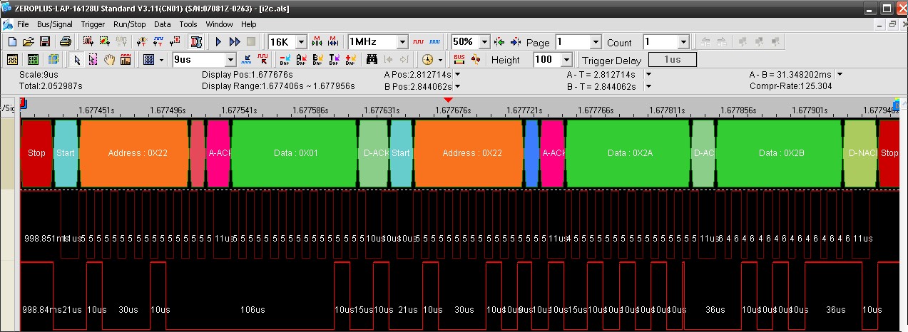
Protocol Analyzer view of an entire Write and Read sequence. The Master first writes the pointer to the first register it wants to read from (0X01). Then a re-start without stop and the Slave send back two bytes (0X2A and 0X2B)
The procedure is executed within the High Priority ISR in order to speed up the response on I2C bus and avoid interruption (too long clock stretching), so an high care must be taken on execution time and on external calls. If there are less strict requirements, the entire procedure can be executed in the main part after the setting of a flag into the ISR.
This execution time optimization lead to a bigger code, without call to external procedures and also with some (usually) deprecated "goto label"
On this picture it is possible to see the response time of the I2C Slave ISR procedure. The clock is stretched (kept low) by the slave, just for half a cycle more (5us). It is a very small overhead after all.
Just to understand how a bad designed slave software can create problems, as slowing down or blocking everything on the entire I2C bus, I've had an experience of a fully blocked Arduino program when, because of an error, I kept the clock line low indefinitely. Maximum care on delays must be taken and a sapient use of the watchdog is required
A porting on a dsPIC33F has be done too. The I2C peripherals in the new PIC 18F series and in the PIC 24F/dsPIC33F series are very similar. A
Microchip document explains the differences. The PIC 24F/dsPIC33F I2C module is more powerful because it has separate buffers for TX and RX, allowing a simultaneous master and slave behavior. This also simplify the code in the dsPIC33 version.